

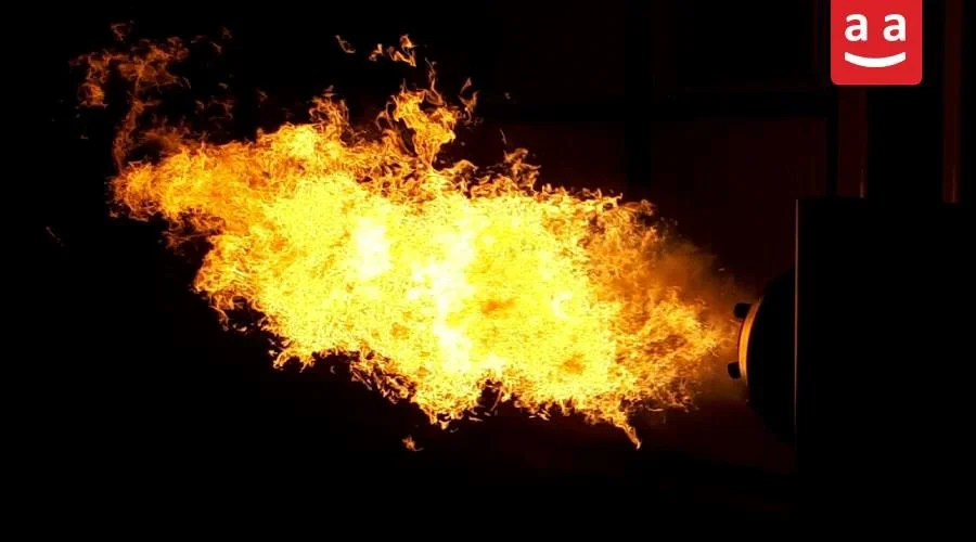
In many buildings and industrial facilities, oil (diesel) is still widely used as a primary fuel for heat generation. Oil burners (diesel burners) operate by atomizing and combusting oil, creating a stable and powerful flame capable of supplying reliable and continuous heat for various heating systems. Their consistent performance makes them a dependable solution in applications where uninterrupted operation is essential.
This article examines different types of oil burners, their main components and parts, common applications, servicing methods, and the most widely used models, providing practical insights to help users make an informed and appropriate choice.
What is an Oil Burner?
An oil burner (diesel burner) is a type of industrial burner that provides the heat or energy needed for heating systems by burning oil. These burners are used in residential and commercial buildings, workshops, and industrial facilities—particularly in locations where natural gas is unavailable or limited.

Raadman Oil Burner – Dual-Fuel (Oil & Gas)
Raadman dual-fuel burners (gas & diesel) are ideal for residential, commercial, and industrial use. Their ability to operate on both gas and oil provides high flexibility under varying fuel supply conditions. When gas supply is limited or a backup fuel is needed, the burner’s switching system enables a smooth transition between fuels without downtime, ensuring continuous operation and full safety compliance.
In Raadman dual-fuel burners, the combustion head and air-fuel mixing system are carefully designed to deliver a stable flame, efficient combustion, and low emissions, whether using oil or gas.
Implementation of staged or electronic modulating control systems reduces operator intervention and maintains precise air-to-fuel ratio control. These designs fully meet BS-EN 676 for gas burners and BS-EN 267 for oil burners.
In addition, achieving a turn-down ratio of up to 1:5 when operating on oil provides a wide adjustment range, enabling more economical operation across different capacities. Certain models are also available in multi-fuel configurations, capable of operating with LPG or heavy fuel oil, giving users the flexibility to choose the burner that best fits the needs of their project.
Discover Raadman dual-fuel burners and find the perfect model for your needs on the Raadman Dual-Fuel Burner Page.
Oil Burner Components
Oil fuel burners consist of several parts and equipment, each designed to manage fuel delivery, air mixing, and the formation of a steady flame. Each component has a distinct role in ensuring the burner operates correctly and maintains stable combustion. Proper integration of these components ensures the burner operates safely, reliably, and at high efficiency. The following describes the main components of an oil burner and the role of each in the system.
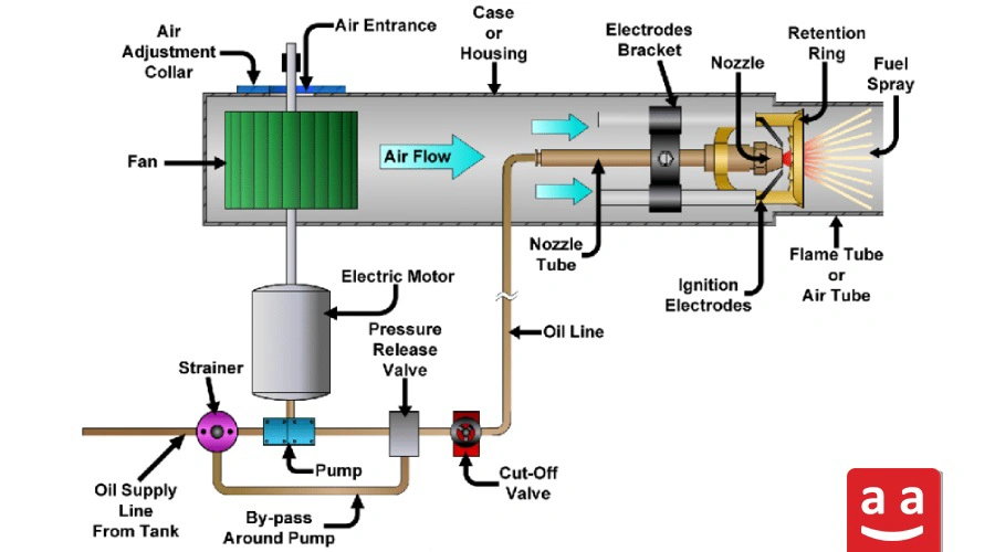
1- Air Supply System: This system, which includes the fan, motor, and air dampers, delivers the necessary air for combustion.
2- Combustion head: The combustion head contains diffusers and swirlers that distribute air within the burner, ensuring a stable flame and low emissions.
3- Fuel Supply System: The fuel supply system manages the delivery of oil to the burner through piping, fuel lance, and nozzles, ensuring proper fuel flow for efficient combustion.
4- Fuel Train: The fuel train carries oil from the tank to the burner and includes filters, pumps, valves, and pressure control devices to ensure safe and stable fuel flow.
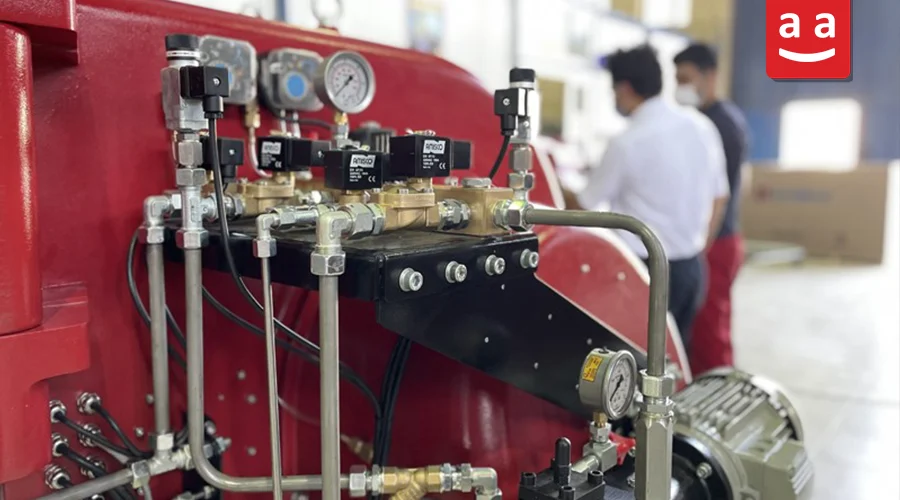
5- Burner Safety System: The safety system monitors the burner using air sensors, pressure switches, and flame detectors to make sure it operates safely at all times.
6- Burner Control System: The burner’s power and control system manages both energy and operation. The power circuit includes relays, contactors, fuses, and the motor starter, while the control circuit handles combustion through relays and processors. Actuators on the air and fuel dampers help adjust airflow and fuel for stable burner operation.
Oil Combustion
In order for oil to burn efficiently, it must be atomized into very fine droplets. This process, known as fuel atomization, increases the contact between fuel and air. The smaller the droplets, the better the mixing with oxygen, resulting in more complete combustion and minimizing unburned fuel, smoke, and emissions.
There are several ways to atomize oil, such as pressure atomization, air or steam atomization, and centrifugal atomization (in rotary cup burners). Each of these methods is described in detail below.
Oil Pressure Atomization
In this method, oil is forced through a very small orifice at high pressure (for example, around 25 bar). The high pressure first breaks the fuel into fine streams and then into tiny droplets. These fine droplets mix better with combustion air, producing a more uniform flame.
The structure of the nozzles that perform this function (pressure atomizers) is shown in the figure below.

Air/Steam Atomization
In this method, oil is atomized using a jet of air or steam. The oil pressure is usually lower than in pressure atomization (for example, up to 10 bar), and the air or steam is introduced at a similar pressure. The mixture passes through a small nozzle, producing very fine droplets for efficient combustion.

Centrifugal Atomization
Centrifugal atomization is commonly used in rotary cup burners. Fuel enters a rotating cup at low pressure, forming a thin layer along the inner walls. Fuel is delivered at relatively low pressure into a rotating cup. As the cup spins, a thin layer of fuel adheres to its inner surface and is pushed outward by centrifugal force. At the edge of the cup, the fuel layer breaks into fine droplets. Concurrently, a high-velocity air jet enhances droplet formation, optimizing fuel-air mixing for stable and efficient combustion.
Due to its specialized structure, this method is well-suited for heavy fuels such as mazut, as it features larger orifices that allow impurities to pass through. For lighter fuels such as oil, rotary cup burners are usually unnecessary, and pressure or air/steam atomization methods are preferred. Overall, this type of burner is specifically designed for heavy and impurity-containing fuels.

Oil Spray Patterns and Flame Performance
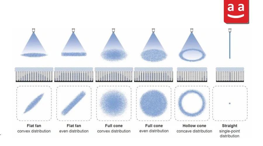
The shape and pattern of oil spray significantly affect combustion quality, fuel consumption, and emissions. Depending on the nozzle type, fuel pressure, and airflow, different types of atomization are formed. Two common patterns are:
Hollow Cone: A hollow, ring-shaped spray that creates finer droplets and even distribution, perfect for burners with low-pressure air.
Full Cone: A solid, conical spray that penetrates the combustion chamber well, ideal when a stronger flame is needed.
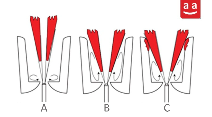
Impact of Oil Spray Angle on Flame Length
Low Angle: Creates smaller air vortices and less air reaches the base of the flame, making it longer.
High Angle: Air circulates back toward the nozzle better, fuel burns faster, and the flame becomes shorter.
Excessive Angle: The flame may contact the combustion chamber walls, potentially causing damage.
The figure below illustrates these three spray angles and their effect on flame formation.
Oil Burner Operation
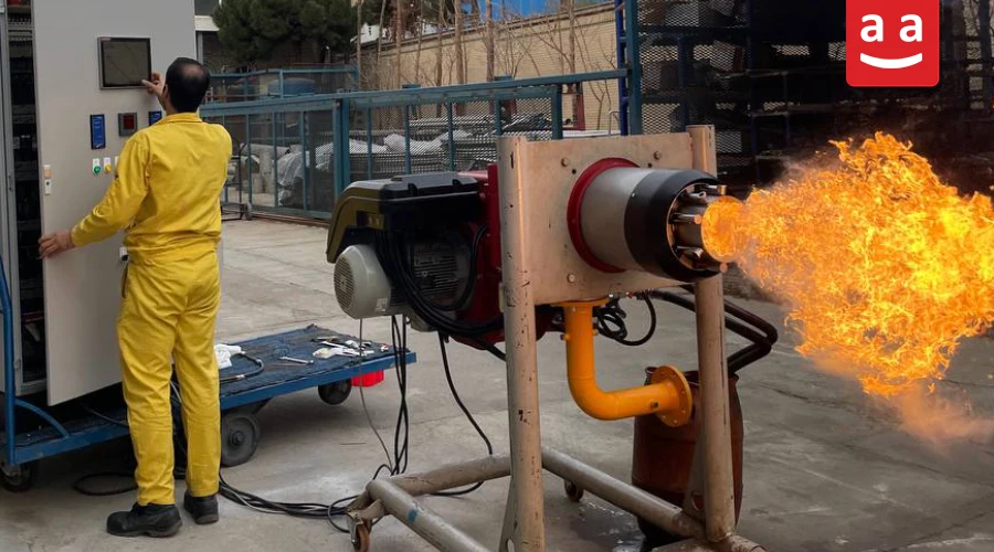
An oil burner (diesel burner) works through a few straightforward but very important steps. Each part plays its role in creating a flame that is stable, safe, and easy to control.

1- Fuel Preparation and Pumping
Initially, the oil pump delivers the fuel to the nozzle at the appropriate pressure. This pressure must remain stable and precise to ensure the proper operation of the burner.
2- Fuel Atomization in Nozzle
Within the nozzle, oil is atomized into very small droplets. The fine dispersion improves fuel-air mixing and promotes thorough and stable combustion.
3- Air Supply and Controlling Oil-to-Air Ratio
Simultaneously with oil injection, the air supply fan delivers the required combustion air into the chamber, while the damper regulates the airflow to maintain the correct air-to-fuel ratio. Precise adjustment ensures a stable flame, reduces fuel consumption, and minimizes smoke and emissions.
4- Ignition and Combustion Start
After the fuel and air are properly mixed, the ignition system ignites them. This creates the flame, allowing the burner to reach steady and reliable operation.
5- Heat Generation and Energy Transfer
The flame generated in an oil burner provides the necessary thermal energy for heating systems, steam boilers, and industrial equipment. Depending on the burner’s capacity, the heat output can range from several hundred kilowatts to multiple megawatts.
Oil Burner Applications
Oil fuel burners are used in a variety of settings to provide steady, controllable heat. Typical applications include:
Hot Water and Steam Boilers: Supplying the heat needed to produce hot water or steam for heating and industrial purposes.
Cement Kilns: Producing high temperatures to process raw materials efficiently, improve product quality, and save fuel.
Ceramic and Tile Kilns: Providing consistent heat for firing ceramics and tiles, improving the strength and finish of the final product.
Applications of Oil Burners Based on Capacity
Oil fuel burners in different heat capacity ranges have different applications:
Capacities below 1 MW: They are typically used in small-scale heating systems, residential and commercial boiler rooms, and light industrial facilities.
Capacities between 1 to 3 MW: This is the most common capacity range for medium-scale industries and workshops. These burners are widely used in hot water and steam boilers for large buildings, painting lines, greenhouses, dairy processing units, industrial bakeries, and drying workshops.
Capacities above 3 MW: They are mainly employed in cement plants, petrochemical refineries, power generation facilities, steel manufacturing industries, and heavy-duty thermal processes that require a continuous and high-temperature heat supply.
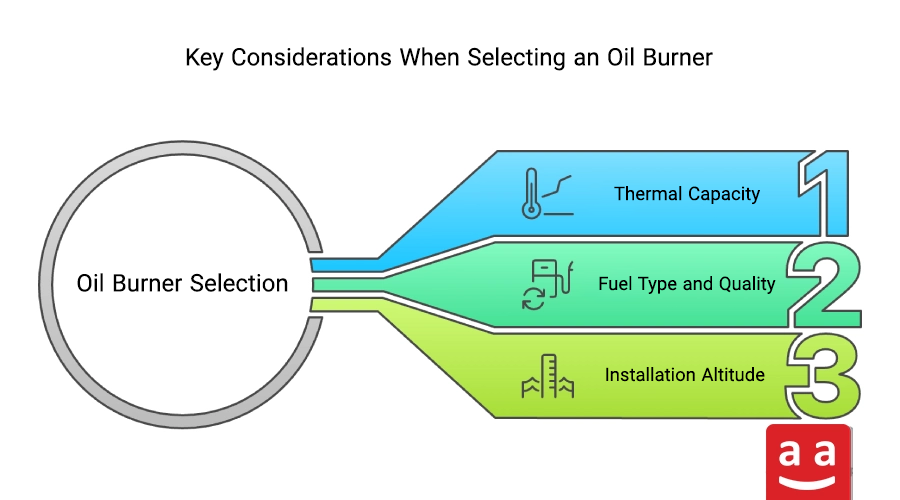
Key Considerations When Selecting an Oil Burner
When selecting an oil burner, several key factors should be considered, as outlined below:
- Thermal Capacity: The oil burner must match the real heat requirement of the system. Excess capacity increases fuel consumption, while insufficient capacity causes poor heating performance.
- Fuel Quality: Using clean, standard-quality fuel as recommended by the manufacturer helps prevent efficiency losses and excessive emissions.
- Installation Altitude: In high-altitude locations, reduced air density leads to lower burner output, which must be considered during system design and burner selection.
Oil Burner Maintenance and Servicing
To ensure stable operation and extended service life, proper maintenance practices must be followed:
1- Regular inspection of the burner and nozzles to confirm stable flame formation and proper operation.
2- Servicing the fuel pump and monitoring fuel pressure to maintain consistent and reliable operation.
3- Optimizing burner firing rate based on system thermal load to improve efficiency and reduce fuel waste.
4- Inspecting and replacing worn or damaged components to prevent unexpected failures.

Oil Burners; An Efficient Solution for Industrial Applications
Oil fuel burners play an essential role in industrial and commercial heating systems by providing consistent and controllable heat output. By delivering uniform heat and minimizing emissions, they meet the requirements of energy-intensive industries such as metal melting, glass, ceramics, and cement production. In regions where access to natural gas is limited or costly, oil burners remain a dependable and cost-effective solution for heat generation.
With a team of experienced specialists and the use of the latest global combustion technologies, Raadman offers a wide range of oil-gas burners with high efficiency and advanced safety standards. To select the most suitable oil burner for your project, you can contact Raadman and benefit from professional technical consultation.
Frequently Asked Questions (FAQ) about Oil Burners
What is an Oil Burner and How Does It Work?
An oil burner generates the heat needed for boilers, furnaces, and heating systems by efficiently mixing oil with air and igniting it.
What Are the Main Components of an Oil Burner?
Key parts of an oil burner include the air fan, fuel spray nozzle, oil pump, ignition system, and the safety control circuit.
Which Industries Use Oil Burners?
These burners are commonly used in hot water and steam boilers, cement, ceramic, and glass kilns, as well as in the food industry and greenhouses.
What Should Be Considered in Selecting an Oil Burner?
The required thermal capacity, fuel quality, altitude conditions, and the type of industrial process are among the key considerations.
How Should an Oil Burner Be Maintained and Serviced?
Regular servicing including flame and nozzle inspections, controlling pump pressure, fuel flow adjustments, and replacement of worn parts leads to a longer service life and enhanced burner efficiency.


2 responses
Good afternoon RAADMAN
This is a simple and elegant review of burner operation- WELL DONE..
Please could you include some detailed information on FLAME TUBE FAILURE.
We have a burner firing Illuminating Paraffin and the SHORT FLAME TUBE fails repeatedly every few weeks. WHY ?
The flame tube is cylindrical from burner for 1 metre and about 350 mm in diameter and of 2mm x 316 stainless steel. Attached to the top of the cylinder is a conical tube of 2 mm x 316 SS and it has tabs fixing it to the cyliner.
The cone has 40 mm diameter holes in it.
the Cone has been torn open and the 40 mm holes have turned inwards..
If only I could send you a FOTO..
Please make contact and sedn us and email address so we can communicate
best wishes
Simon Norton
Cape Town SA
chemdetect@iafrica.com
Thank you for your comment. Our team has contacted you via email to assist you further. Please check your inbox.