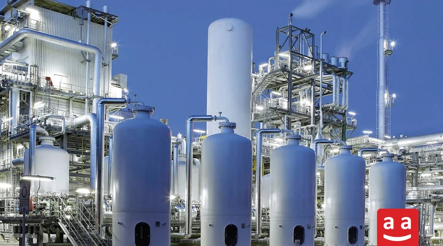

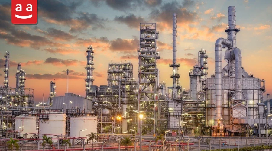
In refinery and petrochemical plants, the reliability and stability of production largely depend on equipment designed for effective heat generation and management. Fired heaters and their burners are among the most critical of these systems, components that may appear simple at first glance but are highly complex and decisive in practice. The design of fired heaters and burners directly influences essential parameters, including combustion efficiency, flame characteristics, heat distribution, fuel consumption, and emissions, thereby playing a crucial role in the overall performance and operational efficiency of petrochemical and refinery units.
In industrial projects, fire heater design and burner selection are considered strategic decisions rather than purely technical issues. Any error in design or operation can result in decreased efficiency, higher energy consumption, equipment degradation, and substantial economic costs. Consequently, gaining a comprehensive understanding of fire heater configurations, burner characteristics, and the criteria governing their selection has become one of the key priorities for engineers working in this field.
For a better understanding of burner operation and their role in thermal systems, you can refer to the article titled “What Is an Industrial Burner?”
What is a Fired Heater?
This is one of the most important process equipment in the oil, gas, and petrochemical industries. It is responsible for providing the necessary heat to warm process fluids such as crude oil, gases, or hydrocarbons. In fired heaters, the heat generated from fuel combustion is used directly for heating purposes, which is the reason behind their name. Fired heaters are among the largest energy consumers in industrial facilities, accounting for approximately 37% of the total energy consumption in U.S. manufacturing industries.
How Does a Fired heater Operate?
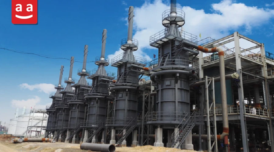
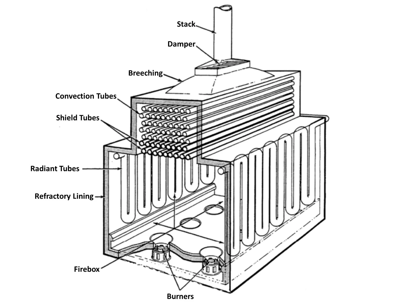
This equipment, depending on its size, is equipped with one or multiple burners that supply the necessary energy by combusting fuel. Along the walls and inside the fired heater, there are numerous tubes through which the process fluid flows. The fluid absorbs heat generated by the burners via three mechanisms—radiation, convection, and conduction until it reaches the desired temperature.
Components of a Fired heater
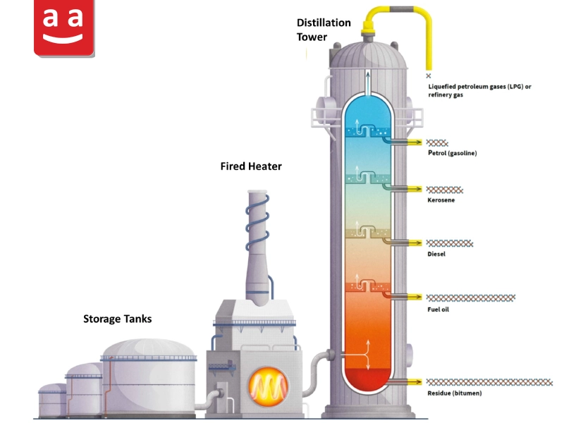
These are relatively large equipment made up of numerous parts and sections. They are designed and constructed in different varieties, but their overall operation is similar, and their main parts are generally the same. The key parts of a fired heater are outlined below.
Fired Heater Burner
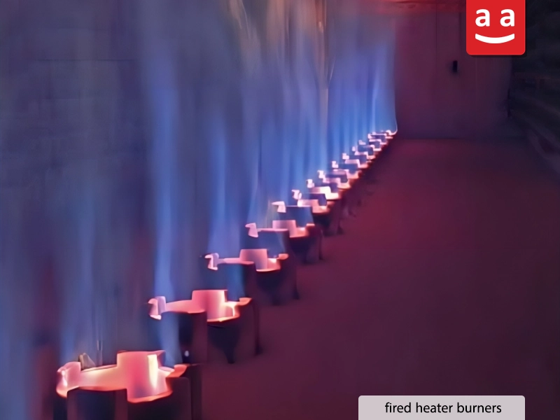
One of the key components of a fired heater is its burner(s), which are installed either on the floor or the walls of it. Their primary function is to burn fuel and generate the heat required for the process. These components play a vital role in determining the overall performance and efficiency of the fired heater. Therefore, the following sections provide a more detailed discussion of their operating principles, features, components, and different types.
Radiant Section of a Fired Heater
The radiant section is the primary heat transfer zone in a fired heater, where the first stage of heat transfer from the burner flames to the process fluid takes place. This section consists of multiple tubes arranged horizontally, vertically, or in a helical configuration around the burners, all enclosed within a refractory-lined and insulated chamber. The main way of heat transfer in this section is Radiation, with thermal energy being transferred primarily through radiant heat emitted by the high-temperature flames to the process tubes. Depending on the fired heater design, approximately 55–85% of the total required heat is absorbed in the radiant section.
Convection Section
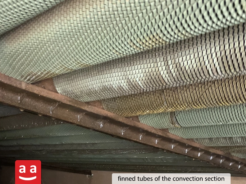
The convection section is where the main heat transfer mechanism is convection, and its name reflects this. This section consists of a series of pipes that are positioned perpendicular to the flow of hot gases generated by combustion, following the radiant section. The process fluid first enters the pipes in the convection section, where it is preheated before flowing into the pipes in the radiant section. The combustion products exiting the radiant section, still at high temperatures, lose some of their energy in this section. As a result, their temperature is significantly reduced.
Shield Section (Shock Section)
Several rows of tubes are positioned between the convection and radiant sections to protect the convection section tubes from direct flame radiation. This area is referred to as the shield section.
Breeching and Stack
The combustion products, after passing over the coils in the convection section, are directed toward the stack and discharged into the atmosphere through it. The intermediate section between the convection section and the stack is called the breeching.
Fired Heater Walls
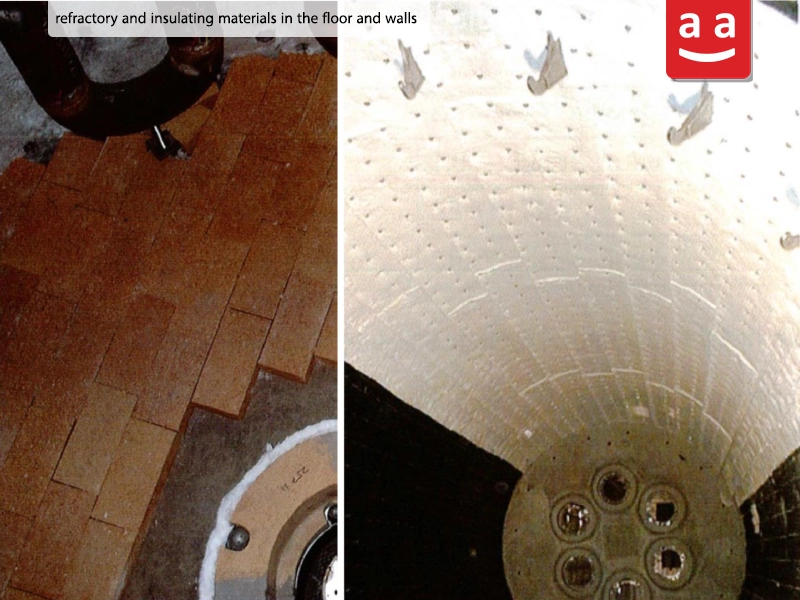
The outer layer of the walls is typically made of steel sheets. On the inner side, the walls and floor are coated with a layer of refractory and insulating materials. This design not only ensures resistance to the intense heat and high temperatures inside the fired heater but also minimizes energy loss.
Types of Fired Heater Configurations
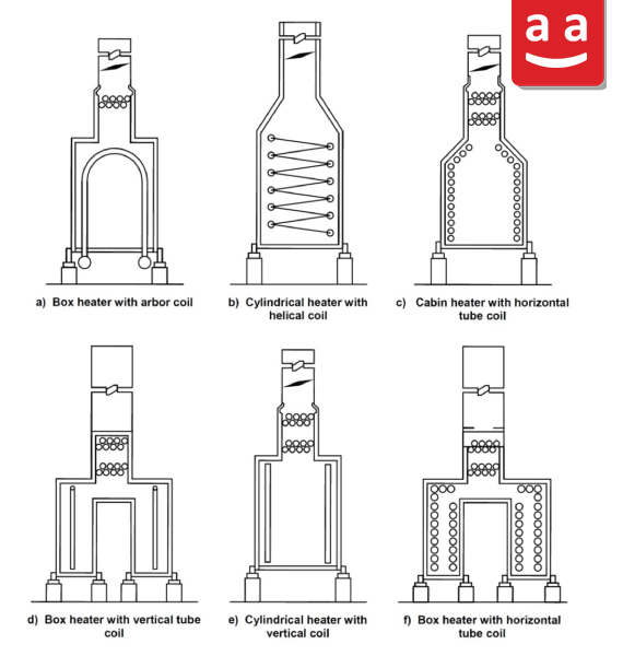
Fired heaters are available in a variety of designs, with different structural configurations and arrangements for the radiant section tubes. The structure may be cylindrical or cubical, while the radiant section tubes can be positioned horizontally, vertically, helically, or in an arbor shape. Examples of these various fired heater configurations are shown in the figure below.
Airflow and Combustion Products in Fired Heaters
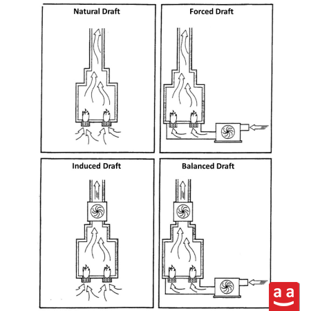
Fire heaters are classified into four categories based on the method of air and hot gas flow within the chamber:
Natural Draft: This is the most common design for fired heaters, which does not require a fan to generate airflow. In this method, the lower density of gases inside the heater compared to the surrounding air creates buoyant forces that drive the flow from bottom to top. This phenomenon, also known as the stack effect, draws air in from the bottom (the burner inlet) and expels combustion products through the stack outlet, the highest point of the fire heater. The intensity of the airflow is dependent on the temperature of the gases inside the heater and its height.
Forced Draft: In this method, air is drawn from the surroundings using a fan and directed into the burner inlet. The fan used in this system is called the FD fan (Forced Draft fan).
Induced Draft: In fired heaters with induced draft, a fan draws air from the outlet of the heater and vents it into the atmosphere. The fan used in this case is called an ID fan.
Balanced Draft: In these fired heaters, an FD fan is located at the inlet and an ID fan at the outlet, with both fans assisting in the movement of gas and air through the heater.
What is a Fired Heater Burner?
Burners are considered the heart of fired heaters. Due to their vital importance in the operation and performance of fired heaters, this article presents a comprehensive discussion of this key equipment.
As mentioned earlier, their main function of burner is to generate the required heat for the fired heater through fuel combustion. Burners must perform this task according to the specific conditions needed by the fired heater to ensure that its performance is optimal in terms of efficiency, safety, cost, and emissions. Therefore, the operation of the fired heater burner must meet the following criteria:
- Creating a stable flame with an appropriate shape to ensure optimal heat transfer to the process fluid.
- Ensuring controlled and safe heating by avoiding hot spots and maintaining even temperature distribution on the tubes.
- Reducing emissions of environmental pollutants like NOx and CO using modern design and state-of-the-art technologies.
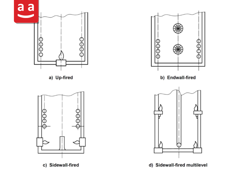
The burners used in fired heaters may be installed either horizontally or vertically on the floor of the combustion chamber or on the walls. The four common burner installation configurations in fired heaters are shown in the figure below.
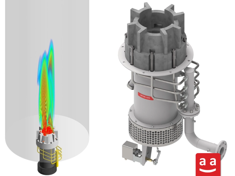
The RSun burners by raadman are specially designed for fired heaters to generate a flame with very low NOx emissions, ensuring that the flame does not impinge the walls and cause damage. These burners come in various sizes and can provide up to 8 MW of capacity in natural draft mode. They are also compatible with forced draft systems, allowing for higher capacity ranges.
Key Features of Fired Heater Burners
As mentioned, fired heater burners must have specific characteristics tailored to the conditions of these units in order to provide optimal, stable, and safe performance.
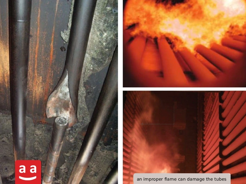
1- Proper Flame Shape: The burner flame in a fired heater must be appropriate for the heater’s operating conditions. If the flame is too long or too thick, it may come into contact with the tubes, causing hot spots and damaging the tubes. Conversely, a very short flame can reduce heat transfer in the radiant section and decrease the overall efficiency of the fired heater. In older fired heater burners, the flame length is generally between 1 to 2 meters per MW, while in newer low-NOx burners it can be up to 2.5 meters per MW. Additionally, in many burners, the flame diameter is about 1 to 1.5 times the diameter of the burner tile.
2- Precise control of the fuel-to-air ratio: To achieve complete combustion with high efficiency and prevent the production of excess pollutants, the fuel-to-air ratio must be optimally adjusted.
3- Stable combustion: Flame instability can lead to reduced efficiency, increased pollutant emissions, and pose financial and safety risks. Therefore, one of the most important parameters in designing fired heater burners is flame stability.
4- Ability to use various fuels: Considering the variety of gases and liquid fuels present in refineries and petrochemical plants, the capability of burners to operate with different fuels becomes very important. The gases in these units include natural gas, hydrogen blends, syngas, and purge gas, while liquid fuels such as oil and mazut may also be used.
5- Minimum emissions: With the growing concern for environmental issues and the tightening of related regulations, older fired heater burners have been replaced with newer Low NOx and Ultra-Low NOx burners. These modern burners use various methods, such as fuel staging, air staging, and flue gas recirculation, to reduce NOx emissions.
Components of a Fired Heater Burner
While fired heater burners may vary in design and configuration, they typically consist of the following key components:
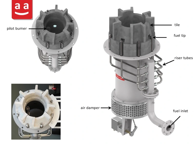
1- Fuel Nozzle (fuel tip)
The fuel tip is responsible for spraying and properly distributing the fuel within the combustion chamber. Burner tips used in fired heaters typically have relatively small holes, with diameters as small as 1.5 mm. Each tip contains one or more holes that inject the fuel at a specific angle and velocity. A burner may have one or several fuel tips positioned in different locations depending on the burner’s design. The design and arrangement of fuel tips significantly influence fuel-air mixing, flame shape, and the emission levels of pollutants such as NOx and CO.
2- Tile
A refractory component (typically with more than 60% alumina content) that forms the burner head and determines the airflow pattern in the combustion zone. The geometry of the burner tile plays a crucial role in fuel-air mixing, flame stability, flame shape, and the recirculation of combustion products, making it a key factor in burner performance.
3- Air Register
The air register controls the flow of air entering the burner to achieve an optimal fuel-to-air ratio and ensure uniform air distribution at the burner head.
4- Pilot Burner
It is a burner with significantly lower capacity than the main burner. It provides a small initial flame to safely ignite the main burner.
5- Fuel Control System and Valves
In the fuel supply line of a burner, a set of control devices including regulators, valves, sensors, and switches is used to regulate fuel flow rate and pressure, and to ensure the safety of the combustion system.
6- Flame Detector
This equipment is part of the safety system and is responsible for detecting the presence of a flame. If the flame goes out, it cuts off the fuel supply to prevent unsafe operating conditions.
Different Types of Fired Heater Burners
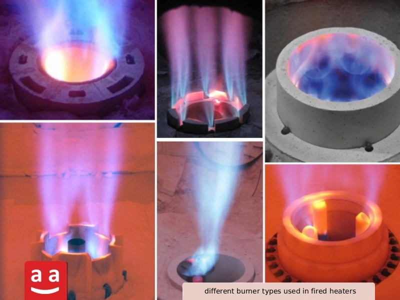
Fired heater burners can be classified based on various criteria:
1) Classification by Airflow Generation Method
One of the most widely used approaches to classify fired heater burners is based on how airflow is generated and managed within the burner system.
Natural Draft Burners: These burners supply air without the use of a fan. The airflow is driven by the difference in density between the hot gases inside the fired heater and the outside air, a mechanism commonly referred to as the “chimney effect.
Forced Draft Burners: In these burners, combustion air is supplied by a fan.
2) Classification by Fuel–Air Mixing Method
Premix Burners: Fuel and air are mixed before entering the combustion chamber, and combustion occurs at the burner head.
Non-Premix Burners (Raw Gas/Nozzle Mix Burners): Fuel and air meet and mix at the burner head, where combustion also initiates.
3) Classification by Fuel Type
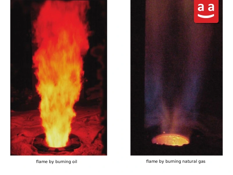
Gas Burners: These burners are designed exclusively for burning gaseous fuels. Gaseous fuels include natural gas, refinery gas, purge gas, and other hydrogen-blended fuels.
For more information about this type, please read the article on Gas Burner Introduction.
Liquid Fuel Burners: Burners designed to operate exclusively on liquid fuels such as oil and mazut.
Dual-Fuel Burners: Designed to use both gas and liquid fuels.
4) Classification by NOx Emission Levels
Burners for fired heaters are typically divided into three groups according to NOx emissions: conventional burners, Low NOx burners, and Ultra-Low NOx burners. While exact thresholds are not strictly defined, the approximate NOx emission levels for each category are:
Conventional Burners: NOx emissions are usually within 80–150 ppm or more.
Low NOx Burners: Emissions typically fall between 30 and 80 ppm.
Ultra-Low NOx Burners: Emissions are under 30 ppm.
Design Standards for Fired Heaters and Fired Heater Burners
The design of fired heaters shall comply with recognized international standards to ensure acceptable levels of thermal performance, safety, and equipment efficiency. The most important reference in this field is API 560, which defines the requirements for the design, materials of construction, fabrication, inspection, testing, and preparation of fired heaters used in the oil and gas industries. Another standard for fired heater design is ISO 13705, which is considered the international equivalent of API 560.
Although API 560 is a general standard covering fired heater design, it also addresses burners, as they are one of the most critical components of fired heaters, by providing relevant requirements and guidelines. In addition, API 535 has been specifically developed for burners used in these devices and specifies requirements related to their performance, specifications, component materials, and testing.
Together, these standards provide a comprehensive framework for their proper design and their burners, enabling the system to operate with high efficiency, optimal safety, and minimum emissions.
The Importance of Proper Fired Heater and Burner Selection
Fired heaters and their burners are among the most critical components in refinery and petrochemical units. The quality of their design and selection directly impacts energy efficiency, operational safety, operating costs, and the environmental performance of the facility. A comprehensive understanding of fired heater design, heat transfer mechanisms, component functions, and particularly the role of the burner, as the heart of the combustion system, is essential for engineers and designers.
Internationally recognized standards such as API 560, API 535, and ISO 13705 provide reliable engineering guidelines for the design, selection, and construction of these systems. However, the overall performance of a fire heater ultimately depends on the proper integration of thermal design, burner selection, combustion optimization, and correct operating practices.
With the advancement of combustion technologies and the introduction of Low NOx and Ultra-Low NOx burners, it is now possible to achieve higher efficiency, improved safety, and significant reductions in emissions simultaneously. Therefore, the intelligent selection of burners and adherence to proven design principles not only optimize fire heater performance but also significantly reduce operating costs and minimize the environmental impact of industrial facilities.
In conclusion, a fired heater may appear to be a simple piece of equipment; however, its design and operation involve complex engineering considerations. Successful and reliable performance depends on a thorough understanding of these complexities and the implementation of advanced combustion technologies.